Sunday, 6 November 2016

SUSPENSION

 SUSPENSION SYSTEM AND TYPES

  • The suspension system of an automobile was one which separates the wheel/axle Assembly from the body. 
  •  The primary function of the suspension system was to isolate the vehicle structure from shocks and vibration due to  irregularities of the road surface. 


     History 

    1903        Mors from Germany fitted a car with shock  absorbers. 
    1920        Layland used torsion bars in its suspension  system. 
    1922       Unitary construction and independent front suspension were pioneered on the Lambda. Lancia       
    1932       By this year ,the independent front suspension become more common in popular cars. 1948       Triumph Mayflower introduced the combined coil spring/damper unit.   
    1950       Ford    adopted the McPherson strut independent    front suspensionon MK 1 consul.
    1959       Use of independent rubber suspension. 
    1962       Introduction of hydrostatic suspension. 

    Function of suspension system 

    •  To prevent the road shocks from being transmitted to the vehicle frame.  
    •  To preserve the stability of the vehicle in pitching or      rolling.  
    • To safeguard the occupants from road shocks.  
    • To provide good road holding while driving, cornering     and braking

    Types of springs

    1. Leaf spring
    2. Coil spring 
    3. Torsion bars
    4. Air and gas sprinG
     5. Rubber spring  

    1. Leaf spring

    Referred to as Laminated springs since they use steel strips or lamination one over the other with reducing length. They are also called as Semi elliptical springs as they are bent in that form.
    Leaf strips are made from strips of spring steel .  Each strip was called a leaf. They are joined together by clamps and a central bolt.  The length of each leaf decreases so that the spring assembly act as a flexible        beam and was of uniform strength.  The ends of master leaf are formed into loops called spring eyes. One end of the spring was attached with frame through a spring bolt passing through the eye. The other end was secured through a shackle . The shackle helps in accommodating the change in length of the spring.


    2.Coil spring 

    • A section of Spring steel rod wound in a spiral pattern or shape. Widely used in both Front and Rear suspension systems. Like large metal bed springs, these coils cushion and absorb the shocks and bumps as the vehicle was driven. They are usually found near the front wheels, but some cars have them in the rear as well. Often the Shock absorbers run up the center of the coil springs. 

    3. Torsion bars

    •  A torsion bar was a solid bar of steel which was connected to the car chassis at one end, and free to move at the other end. They could be mounted across the car or along the car .The springing motion was provided by the metal bar's resistance to twisting. u To over-simplify, stick your arm out straight and get someone to twist your wrist. Presuming that your mate doesn't snap your wrist, at a certain point, resistance in your arm (and pain) would cause you to twist your wrist back the other way. That was the principle of a torsion bar. 
    • Torsion bars are normally locked to the chassis and the suspension parts with splined ends. This allows them to be removed, twisted round a few splines and reinserted, which could be used to raise or lower a car, or to compensate for the natural 'sag' of a suspension system over time. They could be connected to just about any type of suspension system listed on this page. u The rendering below shows an example longitudinal torsion bar. The small lever at the far end of the torsion bar would be attached solidly to the frame to provide the fixed end. The torsion bar itself fits into that lever and the suspension arm at the front through splined holes. As the suspension at the front moves upwards, the bar twists along its length providing the springing motion. 


    4.Air and gas spring
    In these springs compressed air or gasis filledin the cylinder or bellows against which the wheel movement was transmitted through diaphragm. As soon as the wheel passes over a road irregularity the compressed air returns the system to its original position. 
     ADVANTAGES: 1. High cost . 
                                  2.Risk of breakdown. 
                                  3.Freezing of moisture in air in cold weather. 
                                  4.Greater maintenance required.
                                  5.Rubber spring


    Wednesday, 2 November 2016

    Water Jet Machining

    WATER JET MACHINING

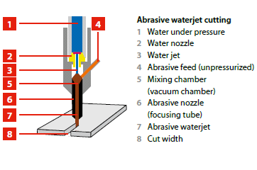
              Water Jet Machining  are two non-traditional or non-conventional machining processes. They belong to mechanical group of non-conventional processes like Ultrasonic Machining and Abrasive Jet Machining . Here, the mechanical energy of water and abrasive phases are used to achieve material removal or machining.
              Water jet machining  can be achieved using different approaches and methodologies as enumerated below:
     • Water Jet Machining  - Pure
     • Water Jet Machining - with stabilizer
     o Direct pumping
     o Indirect pumping
     o Bypass pumping


    WORKING BACKGROUND

    In Water Jet Machining all variants of the processes, The basic methodology remains the same. Water is pumped at a 
      --------->sufficiently high pressure, 
      --------->200-400 MPa  (2000- 4000 bar) [Using intensifier technology].
     An Intensifier works on the simple principle of pressure amplification using hydraulic cylinders of different cross- sections as used in “Jute Bell Presses”. When water at such pressure is issued through a suitable orifice (generally of 0.2- 0.4 mm dia), the potential energy of water is converted into kinetic energy, yielding a high velocity jet (1000 m/s). Such high velocity water jet can machine thin sheets/foils of aluminium, leather, textile, frozen food etc.

    In pure WJM, commercially pure water (tap water) is used for machining purpose. However as the high velocity water jet is discharged from the orifice, the jet tends to entrain atmospheric air and flares out decreasing its cutting ability. Thus stabilisers (long chain polymers) that hinder the fragmentation of water jet are added to the water. 


     APPLICATIONS

    The applications and materials, which are generally machined using WJ and AWJ, are given below: 
     
          • Paint removal 
          • Textile, Leather industry 
          • Mass Immunization 
          • Surgery
          • Cleaning
          • Peening 
          • Cutting 
          • Pocket Milling 
          • Drilling 
          • Turning
          • Cutting soft materials 
          • Cutting frozen meat 
          • Nuclear Plant Dismantling 

    Materials 

              • Polymers
              • Glass Fibre Metal Laminates 
              • Steels 
              • Non-ferrous alloys 
              • Ti alloys, Ni- alloys 
              • Honeycombs 
              • Ceramic Matrix Composite
              • Metal Polymer Laminates
              • Metal Matrix Composite 
              • Concrete  
              • Reinforced plastics 
              • Stone – Granite 
              • Wood

               Other than cutting (machining) high pressure water jet also finds application in paint removal, cleaning, surgery, peening to remove residual stress etc.
              The cutting ability of water jet machining can be improved drastically by adding hard and sharp abrasive particles into the water jet. Thus, WJM is typically used to cut so called “softer” and “easy-to-machine” materials like thin sheets and foils, non-ferrous metallic alloys, wood, textiles, honeycomb, polymers, frozen meat, leather etc, but the domain of “harder and “difficult-to- machine” materials like thick plates of steels, aluminium and other commercial materials, metal matrix and ceramic matrix composites, reinforced plastics, layered composites etc are reserved for AWJM.  


    ADVANTAGES

          • Machine thick plates 
          • Very low side forces during the machining  
          • Machine virtually any 2D shape on every material
          • highly fast set-up and programming
          • Almost no heat generated on the part 
          • Very MINUTE fixturing for most parts 

    SOURCE : NPTEL MECHANICAL : ADVANCED MACHINING TECHNOLOGY