Wednesday, 29 March 2017

POWER STEERING


Introduction to Power Steering
                The purpose of power steering is to reduce the driver’s effort at the steering wheel
•             Almost all modern luxury cars are equipped with power steering system instead of manual steering

•             The power steering is increasingly becoming popular on light, medium and heavy vehicles also
Introduction to Power Steering
•             Power steering system is used in big cars and heavy commercial vehicles whose unladen weight is more than1 500 kg
•             It is useful while driving on rough roads at low speeds and while reversing the vehicle for parking purpose
•             The power steering mechanism employs electrical devices, compressed air and hydraulic pressure

•             The power steering system commonly take assistance of hydraulic power for their operation
•             They become operative when the manual effort exceeds about 1kgf(9.81 N)

•             The system is designed such that if power system fails, it can be operated manually
•             In this situation the driver’s effort will be more such as in manual steering
•             The ‘Power Brakes’ utilise the vacuum and hydraulic powers for their working, but the ‘Power Steering’ utilise hydraulic power only
•             Usually oils of viscosity ratings SAE 5W to 15W flow through the system at about 10 -11kgf/cm2 (1 MPa) pressure
Advantages of Power Steering
•             Lesser steering effort
•             Reduced driver’s fatigue
•             Efficient absorption of shocks
•             Better directional stability

Advantages of Power Steering
•             Higher performance
•             Higher maneuverability
•             Enhanced safety
Types of Power Steering Systems
1.            Integral type  
a.            Rotary spool valve type
b.            Reaction control valve type
2.            Semi-integral type
Ex: Trucks and other Heavy Vehicles
3.            Linkage booster type 
Ex: Rack and pinion type
4.            Speed responding type       
Principles of Power Steering
•             The Power steering is one type of hydraulic device for utilising engine power as steering effort
•             The Engine is used to drive a pump to develop fluid pressure
•             This pressure acts on the piston with in the power cylinder so that the piston assists the rack effort
•             The amount of this assistance depends on the extent of pressure acting on the piston.
•             If more steering force is required, the pressure must be raised.
•             Variation in the fluid pressure is accomplished by a control valve which is linked to the steering main shaft.
                The working principle of a power steering

(a)          Neutral (Straight-ahead ) position
(b)          Turning position can be understood in the next slide

Neutral (Straight-ahead position):

•             Fluid from the pump is sent to the control valve
•             If the control valve is in the neutral position, all the fluid will flow pass through the control valve into the relief port and back to the pump
•             At this time hardly any pressure is created and because the pressure on the cylinder piston is equal on both sides, the piston will not move in either direction

Turning  Position:

•             When the steering main shaft is turned in either direction, the control valve also moves, closing the one of the fluid passages
•             The other passage then opens wider, causing a change in fluid flow volume and at the same time, pressure is created
•             Consequently, a pressure difference occurs between both sides of the piston and piston moves in the direction of low pressure
•             Thus, the fluid in that cylinder is forced back to the pump through the control valve

Steering Gear Booster in a Typical Power Steering System


Parts:
1.Worm      2.Sector   3.Booster cylinder   4.Gear rack   5.Arm
6.Drag link  7.Distibutor slide valve   8. Pipe line
Type Power Steering System
•             A simplified diagram of a hydraulic booster is shown in the previous
•             When the steering wheel is turned, worm (1) turns sector (2) of the worm wheel and arm (5), which turns the wheel by means of drag link (6).
Type Power Steering System
•             If the resistance offered to the turn of the wheels is too high and the effort applied by the driver to the steering wheel is  too weak
•             The worm will be displaced axially (like a screw in a nut) together with distributor slide valve( 7 ) and will thus admit oil (or compressed air) into booster cylinder ( 3) through pipe line (8)
•             The piston will move in cylinder (3) and will turn the wheels via gear rack (4), a toothed sector, arm (5) and drag link (6)
•             At the same time, the worm sector will act upon the worm and will shift with together with the distributor slide valve to its initial position and stop the piston travel
•             When the steering wheel is turned in the other direction, the wheels will be turned appropriately in the same sequence

Various Power Steering Systems 

Various Power Steering Systems

Monday, 27 March 2017

Injection Molding Machine


Injection Molding: Principle and Machinery

Injection molding concept  
               Melt plastic, flow into mold and take part shape, cool, demold


Characteristics:
  1. Injection molding makes parts in discrete (discontinuous) process
  2. More injection molding machines used for plastic processing than any other equipment
  3. Almost all thermoplastic and some thermosets materials can be injection molded
  4. Process is automated with little post-molded finishing and highly repeatable.
  5. Injection molding parts are finished with little post molding operations
  6. Very complex parts can be made
7.  Machines are expensive
8.  Molds are expensive, usually made of P-20 steel
9.  Relatively high amount of scrap (process residue)  - to make a regrind

Injection Molding Machine

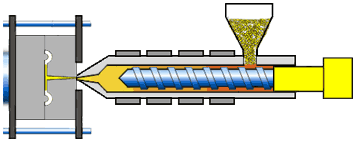
The injection molding machine comprises of three units: 
The injection/plastication unit: to heat, melt and inject the melt into the mold
The Mold and Clamping Unit:
   - Mold: where the product part is shaped
   - Clamp Unit/Press: to press and close the mold, resisting the force from the injected polymer melt (force ~ 150-1000 MPa)
3) The Control Unit:
   computerized control
   all the machine elements


Some Key Terms: for Injection Molding Machines

The control panel

The Injection Units

The injection or plastication unit heats, melts (plasticates) and injects the melt plastic into the mold (through non-returen value and nozzle).
The unit consists of hopper, plasticating screw, non-return value and nozzle
Two general types of injection units are used :
    - the reciprocal-screw type – where the screw rotate-backward when injecting the melt
    - the ram type – where the ram (plunger) is used to push off (inject) the melt
There are also two-stage injection units where the plastication part and injection part are separated, each part can also be either screw or ram type.
Types of The Injection Units
1      
                    Reciprocal Screw Injection 

2                 Ram Injection
Check Valve or Non-return Valve
Check Value: prevent the resin flow when the screw is advanced during resin injection.
The Mold Part

The mold is a steel unit that is mechanically fasten (e.g. bolted) in the clamping unit, but can be replaced for different molding shapes.
 The mold components consist of
1) Cavity/Part/Impression: where the molded products take shaped.  Can have single or multiple cavities in a mold.
2) Channels: where the polymer melt flows
            - Sprue : a channel from nozzle,
            - Runners : run from sprue to individual cavities
            - Gates : narrow gaps at the end of each runner, at the entrance to the cavity. 
3) Cooling channels/Chiller : where cooling water flows to reduce heat
4) Ejector pins : to remove the molded parts from the mold cavities.
   * The mold is very expensive( need a great care & clean storage).
Components of The Mold
A-Plate: stationary plate,  holds cavity insert, sprue bushing, and runner systems
B-Plate: moving plate, holds the core insert and space for ejector pins.

 Picture of The Mold Base

Stationary and Moving plates of the mold:
If the threaded part is being molded, the moving plate needs to have a threaded core pin and unscrewing retraction is performed to reject the molded part.

Turbocharged Direct Injection VS Common Rail Diesel Injection (TDI VS CRDI)


TDI    was ( turbocharged diesel intercooler) or (turbocharged direct injection) and CRDI was ( common rail diesel injection.)


TDI ENGINE:it had 2 variants VGT(variable geometric turbo) and (non variable) normal TDI engine had a fixed turbine.
The TDI engine uses direct injection,where a fuel injector sprays atomised fuel directly into the main combustion chamber of each cylinder, rather than the pre-combustion chamber prevalent in older diesels which used indirect injection. The engine also uses forced induction by way of a turbocharger to increase the amount of air which was able to enter the engine cylinders,and most TDI engines also feature an intercooler to lower the temperature (and therefore increase the density) of the 'charged', or compressed air from the turbo, thereby increasing the amount of fuel that can be injected and combusted.

(VGTs) slightly different design to avoid turbo lag causing by low speed, usually designed to allow the effective aspect ratio (A:R) of the turbo to be altered as conditions change. This was done because optimum aspect ratio at low engine speeds was very different from that at high engine speeds. 

If the aspect ratio was too large, the turbo will fail to create boost at low speeds; if the aspect ratio was too small, the turbo will choke the engine at high speeds, leading to high exhaust manifold pressures, high pumping losses, and ultimately lower power output.

By altering the geometry of the turbine housing as the engine accelerates, the turbo's aspect ratio can be maintained at its optimum

A CRDi engine had rails that inject the fuel into the engine, which was designed to handle higher pressure than an ordinary diesel engine "thereby having results in fuller combustion and efficiency. Since the development of the diesel engine almost a century ago, the focus had been on increasing the fuel injection pressure.In CRDi, the high fuel injection pressure was generated by a supply pump storing in a reservoir the fuel under high pressure in a central container (rail) and delivering to the individual injection valves (injectors) on demand