Metal
extrusion
Process
Extrusion
is a compression process in which work metal is forced to flow through a die
opening to produce a desired cross-sectional shape. The process is like
squeezing toothpaste out of a toothpaste tube. Lubricant is provided to ease
the passage of the metal through the die. Extrusion process is usually
classified based on the physical configuration and working temperature.

Based on physical configuration it is
classified as: direct extrusion and indirect extrusion. Direct extrusion is
also called forward extrusion. In the direct extrusion process the metal billet
is loaded into the container and the ram compresses the metal billet.

The flow
of material occurs in the direction of application of force through the
opposite end as shown in the Figure M4.1.1. Hollow sections are possible to
create by this process setup as shown in Figure M4.1.2. Indirect extrusion is
also called backward extrusion process. In the backward extrusion process, the
die is mounted on the ram. As the ram penetrates into the work, the metal is
forced to flow through the die in the opposite direction of motion of the ram
as shown in the Figure M4.1.3.

Figure
M4.1.1: Direct Extrusion

Figure
M4.1.2: Direct Extrusion to produce hollow cross-section

Figure
M4.1.3: Indirect Extrusion
Based on working temperature,
classification of extrusion is as: hot extrusion and cold extrusion. Hot
extrusion involves prior heating of billet to a temperature above its
crystallization temperature. Cold extrusion is usually used to produce parts at
room temperature.
Typical
parts and applications
Any
part with constant cross-section can be produced by this method. Cross-section
that can’t be produced by normal machining process are often more economical by
the extrusion process. A standard method of measuring capacity is used called
circumscribing–circle-diameter (CCD). This is the size of circle into which the
cross section will fit. For aluminum, the minimum CCD is 6.3mm and maximum CCD
is 1.02m. For steel the diameter is small. Maximum CCD for steel is 150mm. In
fact, extrusion over 30m in length and 1 Ton in weight can be made. Wall
thickness for aluminum ranges from 1mm upward. For carbon steel, the minimum is
3.2 mm and for stainless alloys 4.8mm.
Suitable
material for extrusion
Two
factors affect the ease with which the metal can be extruded namely, required
temperature and the temperature range. If the required temperature for
extrusion is low and available temperature range is wide the extrusion will be
better. The most common metals used for the extrusion are the following (listed
in order of extrudability):
1. Aluminum and aluminum alloys
2. Copper and copper alloys
3.Magnesium
4.Low-carbon and medium-carbon steels
5.Modified-carbon steels
6.Low-alloy steels
7.Stainless steels
General
design recommendation
Though
complicated shapes are possible to create, it is advisable to use standard
cross-section whenever possible as shown in Figure M4.1.4.

Figure M4.1.4: Standard extruded shapes
available.
The
problem with complicated shapers are: metal flows less readily into narrow and
irregular die section, distortion and other quality problems, price of the
customized dies are higher.
Detail
design recommendation
The
various design recommendations are as follows:
Sharp corners are avoided for both internal and external corner of extruded
part. If sharp corners are used various problems encountered are: less smooth
flow of material through the die, increase tool wear, increased possibility of
tool breakage, less strength in the part due to stress concentration.
Recommended minimum radii for various metals and alloys are summarized in Table
M4.1.1 for guidance. Figure M4.1.5 shows the good and bad practice in the
design of cross-section of component to be extruded.

Figure
M4.1.5: Good and bad practice in the design of cross-sections to be extruded
Table
M4.1.1: Recommended minimum corner and fillet radii. (Source: Design for
Manufacturability Handbook by James G Bralla, 2nd Ed)

- Section walls should be balanced as much as the design function permits as shown in Figure M4.1.5.
- Ribs are added in order to avoid the variation of flatness of a long thin section those having critical flatness requirement as shown in Figure M4.1.6.

Figure
M4.1.6: Ribs are added to the sections for long sections.
- Knife like edge part is avoided because it affects smooth flow of material through die. Holes in nonsymmetrical shapes should be avoided in less extrudable material as shown in Figure M4.1.7.

Figure
M4.1.7: Knife edge should be avoided.
- Abrupt changes in section thickness are avoided for less extrudable materials like steel as shown in Figure M4.1.8.

Figure
M4.1.8: Avoid abrupt changes in section thickness for less extrudable materials
- Recommendations for depth of indentation has been shown in the Figure M4.1.9.
Can’t
be extruded in steel Can be extruded in steel
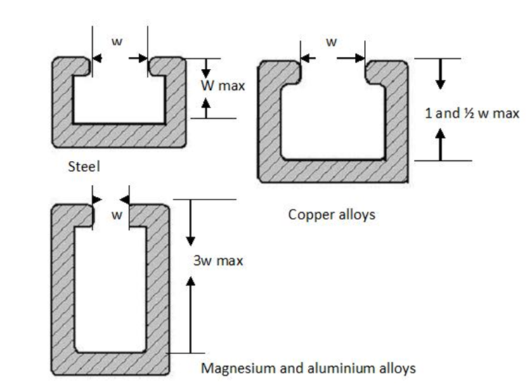
Figure
M4.1.9: Design rules for indentations.
- The ratio of length to thickness of any segment should not exceed 14:1. For magnesium it is 20:1 as shown in Figure M4.1.10.

Figure
M4.1.10: The length-to-thickness ratio of any section of an extrusion of steel
or other difficult-to-extrude material should not exceed14.
- Symmetrical cross sections are preferable to non-symmetrical designs to avoid unbalanced stresses and warpage. Design recommendation has been shown in the Figure M4.1.11.

Figure
M4.1.11: Nonsymmetrical shape by extruding asymmetrical section and dividing it
in two.
Dimensional
factor
Extrusion
is a hot process and temperature and cooling rate variation affect the final
dimension of the extruded parts. Hence, extruded parts are more inherent to
piece-to-piece and drawing-topiece dimensional variation than parts made with
other processes.
Recommended
tolerances
Table
M4.1.2 summarizes the recommended tolerances for extruded parts for ferrous
metal.
Table
M4.1.2: Recommended Dimensional Tolerances for Ferrous-Metal Extrusions.
(Source: Design for Manufacturability Handbook by James G Bralla, 2nd Ed)

Table
M4.1.3: Recommended Dimensional Tolerances for Ferrous-Metal Extrusions.
(Source: Design for Manufacturability Handbook by James G Bralla, 2nd Ed)

Wow! This is an ultra-informative post that pretty much details anything one could want to know about this particular extrusion process. I will certainly go back from time to time and use this as reference. I do hope that you post more of these as they really simplify all of the procedures.
ReplyDeleteBrandi Bradley @ Rotax Metals
thank you :)
Delete